Make a RFID Lock System With Servo Using Raspberry pi 4

Radio Frequency Identification (RFID) is a technology that uses radio waves to passively identify a tagged object. It is used in several commercial and industrial applications, from tracking items along a supply chain to keeping track of items checked out of a library.
Project Video
Overview

In this tutorial we will create our own smart lock using an RFID lock system that requires a unique card to perform a specific action. In our case, we will use it to open a door with a servo motor.
Getting the Items
Steps
First, enable the SPI in the Raspbian system by clicking on the menu, then preferences, then Raspberry pi configuration, and from the interfaces, enable the button next to the SPI field, as in the image below:

Now we must install some libraries so that we can use the RFID with the Raspberry Pi 4 board without problems. Enter these commands in order in the terminal:
• sudo apt-get update
• sudo apt-get upgrade
• sudo apt-get install python3-dev python3-pip
• sudo pip3 install spidev
• sudo pip3 install mfrc522
Wiring it Up

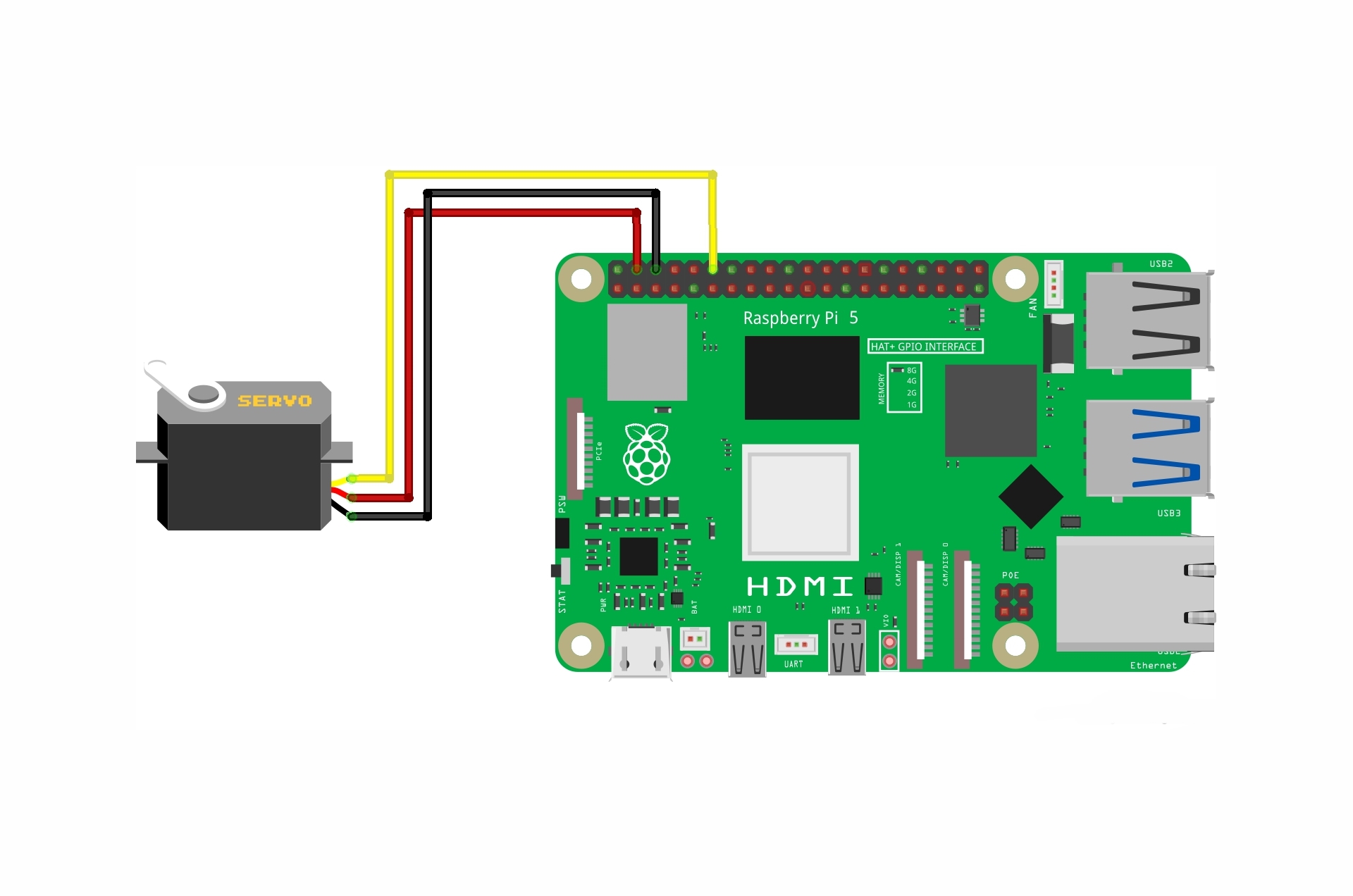
Connect the wires between the MFRC522 RFID module and the servo and leds and Raspberry Pi 4 board, as shown in the image below.

Connections from the Raspberry pi 4 to the breadboard :
• Raspberry pi 4 GPIO GND pin → Breadboard ground line
• Raspberry pi 4 GPIO 3.3V pin → Breadboard VCC line
Connections from the RFID module :
• RFID 3.3V pin →Breadboard VCC line
• RFID RST pin →Raspberry pi 4 GPIO 25 pin
• RFID GND pin →Breadboard ground line
• RFID IRQ pin →unconnected
• RFID MISO pin →Raspberry pi 4 GPIO 9 pin
• RFID MOSI pin →Raspberry pi 4 GPIO 10 pin
• RFID SCK pin →Raspberry pi 4 GPIO 11 pin
• RFID SDA pin → Raspberry pi 4 GPIO 8 pin
Connections from the servo motor:
• Servo GND pin→ Breadboard ground line
• Servo VCC pin→ Breadboard VCC line
• Servo signal pin → Raspberry pi 4 GPIO pin 12
Connections from the white LED :
• LED anode pin → 220 ohm resistor → Raspberry pi 4 GPIO pin 16
• LED cathode pin → Breadboard ground line
Connections from the red LED :
• LED anode pin → 220 ohm resistor → Raspberry pi 4 GPIO pin 20
• LED cathode pin → Breadboard ground line
Coding
Now on your Raspberry Pi, click on the menu, then choose programming, then open the Thonny ide program.

Now copy that code into it, The function of this code is to open a door with a servo motor. print the card ID on a window when the correct card is placed on the RFID sensor, the white LED will light up, but if the wrong card is placed, the red LED will light up and the servo will not move.

Testing it Out

Now run the code, you will find that the Raspberry Pi 5 board opens a door with a servo motor. print the card ID on a window when the correct card is placed on the RFID sensor, the white LED will light up, but if the wrong card is placed, the red LED will light up and the servo will not move.


